Jako základ používám tent projekt https://github.com/TheDIYGuy999/Rc_Engine_Sound
Plán je nahradit i jinou elektroniku v autě jmenovitě světelný modul a řídící jednotky navijáků.
Motory navijáků budu ovládat pomocí L298N: https://www.aliexpress.com/item/32977306174.html
Plán je následující.
Vyhodit z programu nepotřebné části a uvolnit tak piny. Pár pinů přemístit aby vysledné zapojení bylo jednodušší.
Piny plánuji užít takto:
A0 Input - jumper pro režim svícení
A1 Input - RC prijimac CH1
A2 Input - RC prijimac CH2 (v původním programu D2)
A3 Input - RC prijimac CH3
A4 Input - RC prijimac CH4
A5 Input - RC prijimac CH5
A6 volný
A7 volný
D0 Output - Světlomety
D1 Output - Světelná rampa
D2 Output - Zpátečka
D3 Output - Momentálně Repro. (Pry by mělo jít přesunout na D11 Potom by zde byli brzdová světla)
D4 Output - Digitální potenciometr
D5 Output - Digitální potenciometr
D6 Output - Digitální potenciometr
D7 Output - Naviják 1
D8 Output - Naviják 1
D9 Output - Naviják 2
D10 Output - Naviják 2
D11 Output - Brzdová světla (pokud nepujde přehodit repro)
D12 Output - Levý Blinkr
D13 Output - Pravý Blinkr
První co jsem udělal bylo vyházet části které nepotřebuji.
SPI, řízení potenciometrem
Smazány tedy byli řádky 51-55, 68-74,116-124, 144-160, 348-356
K tomu samozřejmě přizpůsobeny řádky 100-107.
A v settings.H zmizel řadek 23 #define POT_PIN A1
Timhle jsem si uvolnil piny A0,A1,A2,D10,D12 pro moje účely. A kod se na dev boardu chová jak by měl.
V tuhle chvíli se snažím přesunout vstup signálu z D2 na A2. Jediné definice vidím na řádku 77 (pinmode) a 332 kde zněj čte (pro zjednoduššení nahrazeno příkazem digitalread(a2))
Výsledkem je, že zvuk je generován jen pokud přivedu signál současně na piny A2 a D2. Přehlížím nějakou kontrolu či definici?
Pokud se pokusím řádek 22 #define SPEAKER 3 změnit na #define SPEAKER 11 tak zvuk není ani na pinu 3 ani 11. To budu muset asi kouknout do části PCM setup (238) jak to posílá zvuk ven. Hádám, že asi přes nějaký registr.
Uvítal bych jestli by na to někdo kouknul a řekl mi kam zaměřit moji pozornost případně mi řekl, zda piny co plánuji požít neblokuje něco jiného.
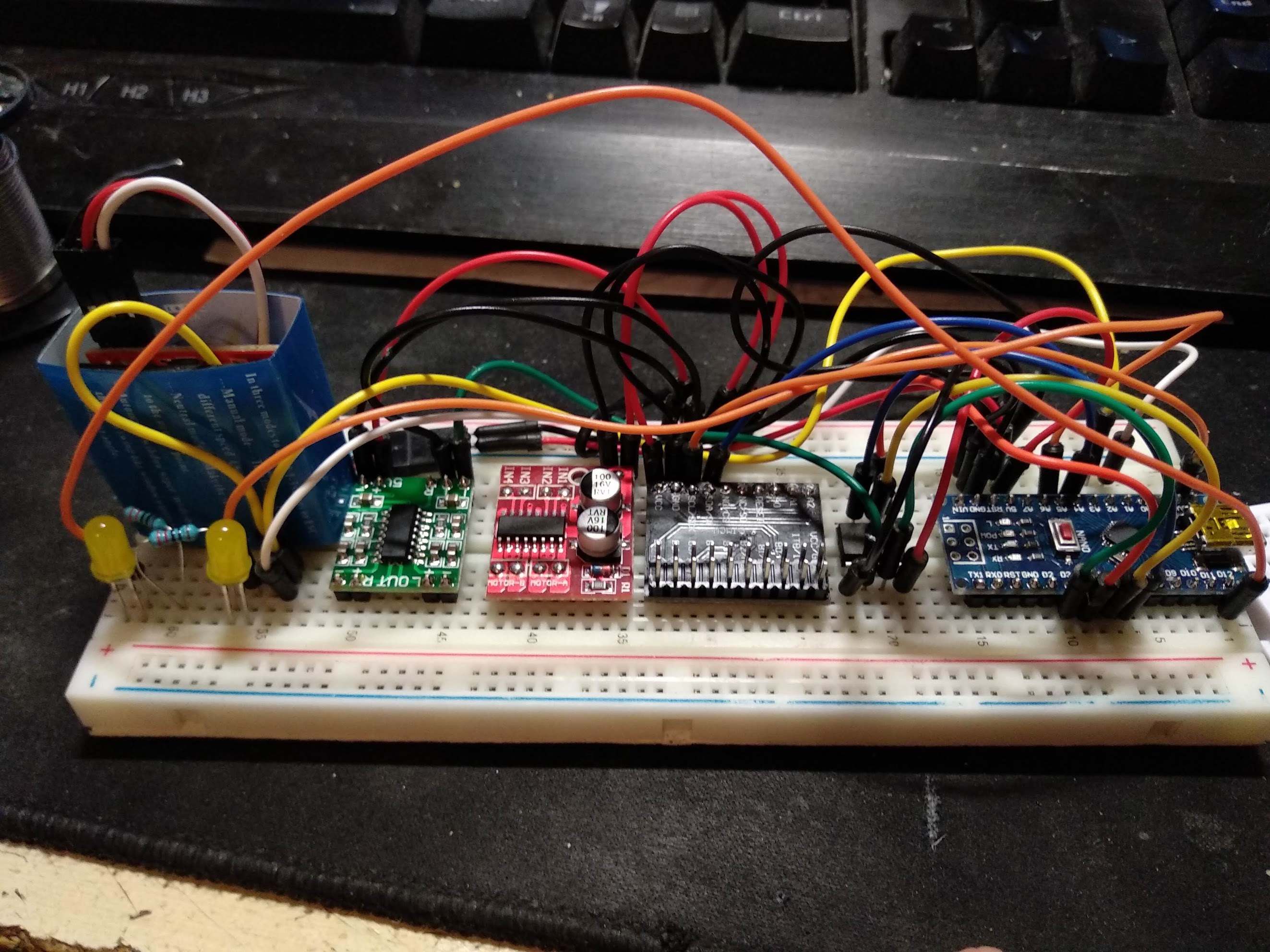
Takhle vypadá aktuálni stav se kterým si hraju.
Kód: Vybrat vše
/*
      This code was quick and dirty, based on a PCM audio example in the
      arduino playground: http://playground.arduino.cc/Code/PCMAudio

      It's been heavely modified for use with RC to generate something that's
      a bit like an engine sound. I've started work on making the program
      readable, still some to do though.
      https://github.com/BeigeMatchbox/mojoEngineSim/blob/master/README.md

      Enhancements, done by TheDIYGUY999 in january 2017: https://github.com/TheDIYGuy999/Rc_Engine_Sound
        - more sounds added,
        - also works on a 8MHz MCU, but not in servo throttle mode
*/

// All the required settings are done in settings.h!
#include "settings.h" // <<------- SETTINGS

const float codeVersion = 1.2; // Software revision

// Stuff not to play with! ----------------------------------------------------------------------------
#define SPEAKER 3 // This is kept as 3, original code had 11 as option, but this conflicts with SPI
volatile uint16_t currentSmpleRate = BASE_RATE; // Current playback rate, this is adjusted depending on engine RPM
boolean audioRunning = false;                   // Audio state, used so we can toggle the sound system
boolean engineOn = true;                        // Signal for engine on / off
uint16_t curVolume = 0;                         // Current digi pot volume, used for fade in/out
volatile uint16_t curEngineSample;              // Index of current loaded sample
uint8_t  lastSample;                            // Last loaded sample
int16_t  currentThrottle = 0;                   // 0 - 1000, a top value of 1023 is acceptable
uint8_t  throttleByte = 0;                      // Raw throttle position in SPI mode, gets mapped to currentThrottle
uint8_t  spiReturnByte = 0;                     // The current RPM mapped to a byte for SPI return
volatile int16_t pulseWidth = 0;                // Current pulse width when in PWM mode
volatile boolean pulseAvailable;                  // RC signal pulses are coming in
#define FREQ 16000000L                          // Always 16MHz, even if running on a 8MHz MCU!

int16_t pulseMaxNeutral; // PWM throttle configuration storage variables
int16_t pulseMinNeutral;
int16_t pulseMax;
int16_t pulseMin;
int16_t pulseMaxLimit;
int16_t pulseMinLimit;

//
// =======================================================================================================
// MAIN ARDUINO SETUP (1x during startup)
// =======================================================================================================
//

void setup() {


  // MCP4131 digi pot
  pinMode(POT_CS, OUTPUT);
  pinMode(POT_SCK, OUTPUT);
  pinMode(POT_SDO, OUTPUT);
  digitalWrite(POT_CS, HIGH);
  digitalWrite(POT_SCK, HIGH);
  digitalWrite(POT_SDO, HIGH);

  if (managedThrottle) writePot(0);
  else writePot(DEFAULT_VOLUME);

  // pwm in setup, for a standard servo pulse
  pinMode(2, INPUT); // We don't want INPUT_PULLUP as the 5v may damage some receivers!
  if (pwmThrottle) { // And we don't want the interrupt firing when not in pwm mode
    attachInterrupt(0, getPulsewidth, CHANGE);
  }

  // Calculate throttle range
  pulseMaxNeutral = pulseZero + pulseNeutral;
  pulseMinNeutral = pulseZero - pulseNeutral;
  pulseMax = pulseZero + pulseSpan;
  pulseMin = pulseZero - pulseSpan;
  pulseMaxLimit = pulseZero + pulseLimit;
  pulseMinLimit = pulseZero - pulseLimit;

  // setup complete, so start making sounds
  setupPcm();
}

//
// =======================================================================================================
// MAIN LOOP
// =======================================================================================================
//

void loop() {
  if (pwmThrottle) {
    doPwmThrottle();
    noPulse();
  }
  if (managedThrottle) manageSpeed();
}

//
// =======================================================================================================
// THROTTLES
// =======================================================================================================
//


// RC PWM signal -------------------------------------------------------------------------------------
void doPwmThrottle() {

  if (pulseWidth > pulseMinLimit && pulseWidth < pulseMaxLimit) { // check if the pulsewidth looks like a servo pulse
    if (pulseWidth < pulseMin) pulseWidth = pulseMin; // Constrain the value
    if (pulseWidth > pulseMax) pulseWidth = pulseMax;

    if (pulseWidth > pulseMaxNeutral) currentThrottle = (pulseWidth - pulseZero) * 2; // make a throttle value from the pulsewidth 0 - 1000
    else if (pulseWidth < pulseMinNeutral) currentThrottle = abs( (pulseWidth - pulseZero) * 2);
    else currentThrottle = 0;
  }

  if (!managedThrottle) {
    // The current sample rate will be written later, if managed throttle is active
    currentSmpleRate = FREQ / (BASE_RATE + long(currentThrottle * TOP_SPEED_MULTIPLIER));
  }
}


//
// =======================================================================================================
// MASS SIMULATION
// =======================================================================================================
//

void manageSpeed() {

  static int16_t prevThrottle = 0xFFFF;
  static int16_t currentRpm = 0;
  const  int16_t maxRpm = 8184; //8184
  const  int16_t minRpm = 0;

  static unsigned long throtMillis;
  static unsigned long startStopMillis;
  static unsigned long volMillis;

  // Engine RPM -------------------------------------------------------------------------------------
  if (millis() - throtMillis > 5) { // Every 5ms
    throtMillis = millis();

    if (currentThrottle + 18 > currentRpm) {
      currentRpm += 18;
      if (currentRpm > maxRpm) currentRpm = maxRpm;
      prevThrottle = currentThrottle;

    }
    else if (currentThrottle - 12 < currentRpm) {
      currentRpm -= 12;
      if (currentRpm < minRpm) currentRpm = minRpm;
      prevThrottle = currentThrottle;
    }

    if (currentRpm >> 2 < 255) spiReturnByte = currentRpm >> 2;
    else spiReturnByte = 255;
    if (currentRpm >> 2 < 0) spiReturnByte = 0;

    currentSmpleRate = FREQ / (BASE_RATE + long(currentRpm * TOP_SPEED_MULTIPLIER) );
  }

  // Engine volume (for MCP4131 digipot only) -------------------------------------------------------
  if (millis() - volMillis > 50) {
    volMillis = millis();

    int vol = map(currentThrottle, 0, 1023, VOL_MIN, VOL_MAX);

    if (vol > curVolume) curVolume = vol;
    else {
      curVolume -= (curVolume / 10);
      if (curVolume < VOL_MIN) curVolume = VOL_MIN;
    }

    int lastVolume = 0xFFFF;
    if (curVolume != lastVolume) {
      lastVolume = curVolume;
      writePot(curVolume);
    }
  }
}

// Write pot subfunction -----------------------------------------------------------------------------
void writePot(uint8_t data) {
  // This function should get a value from 0 - 127
  // It would be trivial to convert this to work with
  // an I2C device.

  if (data > VOL_MAX) data = VOL_MAX; // cap it just in case

  digitalWrite(POT_CS, LOW);
  shiftOut(POT_SDO, POT_SCK, MSBFIRST, 0x00);
  shiftOut(POT_SDO, POT_SCK, MSBFIRST, data);
  digitalWrite(POT_CS, HIGH);
}

//
// =======================================================================================================
// PCM setup
// =======================================================================================================
//

void setupPcm() {

  pinMode(SPEAKER, OUTPUT);
  audioRunning = true;

  // Set up Timer 2 to do pulse width modulation on the speaker pin.
  ASSR &= ~(_BV(EXCLK) | _BV(AS2));                         // Use internal clock (datasheet p.160)

  TCCR2A |= _BV(WGM21) | _BV(WGM20);                        // Set fast PWM mode  (p.157)
  TCCR2B &= ~_BV(WGM22);

  TCCR2A = (TCCR2A | _BV(COM2B1)) & ~_BV(COM2B0);           // Do non-inverting PWM on pin OC2B (p.155)
  TCCR2A &= ~(_BV(COM2A1) | _BV(COM2A0));                   // On the Arduino this is pin 3.
  TCCR2B = (TCCR2B & ~(_BV(CS12) | _BV(CS11))) | _BV(CS10); // No prescaler (p.158)

  OCR2B = pgm_read_byte(&idle_data[0]);                     // Set initial pulse width to the first sample.

  // Set up Timer 1 to send a sample every interrupt.
  cli();

  TCCR1B = (TCCR1B & ~_BV(WGM13)) | _BV(WGM12);             // Set CTC mode (Clear Timer on Compare Match) (p.133)
  TCCR1A = TCCR1A & ~(_BV(WGM11) | _BV(WGM10));             // Have to set OCR1A *after*, otherwise it gets reset to 0!

  TCCR1B = (TCCR1B & ~(_BV(CS12) | _BV(CS11))) | _BV(CS10); // No prescaler (p.134)

  OCR1A = FREQ / BASE_RATE;                                // Set the compare register (OCR1A).
  // OCR1A is a 16-bit register, so we have to do this with
  // interrupts disabled to be safe.

  TIMSK1 |= _BV(OCIE1A);                                   // Enable interrupt when TCNT1 == OCR1A (p.136)

  lastSample = pgm_read_byte(&idle_data[idle_length - 1]);
  curEngineSample = 0;
  sei();


  uint8_t target = map(currentThrottle, 0, 1023, VOL_MIN, VOL_MAX); // Fadein the volume pot
  for (uint8_t i = 0; i < target; i ++) {
    curVolume = i;
    writePot(curVolume);
    delay(1);
  }
}

// ----------------------------------------------------------------------------------------------
void stopPlayback() {

  // Fadeout the volume pot
  for (uint8_t i = curVolume; i > 0; i--) {
    curVolume = i;
    writePot(i);
    delay(1);
  }

  audioRunning = false;

  TIMSK1 &= ~_BV(OCIE1A); // Disable playback per-sample interrupt.
  TCCR1B &= ~_BV(CS10);   // Disable the per-sample timer completely.
  TCCR2B &= ~_BV(CS10);   // Disable the PWM timer.

  digitalWrite(SPEAKER, LOW);
}

//
// =======================================================================================================
// NO RC SIGNAL PULSE?
// =======================================================================================================
//

void noPulse() {
  static unsigned long pulseDelayMillis;

  if (pulseAvailable) pulseDelayMillis = millis(); // reset delay timer, if pulses are available

  if (millis() - pulseDelayMillis > 100) {
    engineOn = false; // after 100ms delay, switch engine off
    curEngineSample = 0; // go to first sample
  }
  else engineOn = true;
}

//
// =======================================================================================================
// INTERRUPTS
// =======================================================================================================
//

// Uses a pin change interrupt and micros() to get the pulsewidth at pin 2 ---------------------------
void getPulsewidth() {
  unsigned long currentMicros = micros();
  boolean currentState = digitalRead(2);
  static unsigned long prevMicros = 0;
  static boolean lastState = LOW;

  if (lastState == LOW && currentState == HIGH) {    // Rising edge
    prevMicros = currentMicros;
    pulseAvailable = true;
    lastState = currentState;
  }
  else if (lastState == HIGH && currentState == LOW) { // Falling edge
    pulseWidth = currentMicros - prevMicros;
    pulseAvailable = false;
    lastState = currentState;
  }
}


// This is the main playback interrupt, keep this nice and tight!! -----------------------------------
ISR(TIMER1_COMPA_vect) {
  OCR1A = currentSmpleRate;

  if (curEngineSample >= idle_length) { // Loop the sample
    curEngineSample = 0;
  }

  if (engineOn) {
    OCR2B = pgm_read_byte(&idle_data[curEngineSample]); // Volume
    curEngineSample++;
  }
  else OCR2B = 255; // Stop engine (volume = 0)
}